Pulse-width modulation is the simplest useful LED project on an FPGA—and one of the best ways to learn counters, clock enables, parameterized RTL, and self-checking simulation. This tutorial builds a reusable VHDL-2008 PWM core, derives its frequency and resolution, and verifies that the output duty cycle matches the requested brightness.
What we are building
VHDL-2008 reference implementation
This article uses synthesizable VHDL-2008. The complete tested VHDL bundle is linked below; adapt clock constraints, I/O standards, and timing parameters to the target board and panel.
library ieee;
use ieee.std_logic_1164.all;
use ieee.numeric_std.all;

entity led_pwm is
  generic (BITS : positive := 8);
  port (
    clk       : in  std_logic;
    rst       : in  std_logic;
    level     : in  unsigned(BITS - 1 downto 0);
    pwm_out   : out std_logic
  );
end entity;

architecture rtl of led_pwm is
  signal counter      : unsigned(BITS - 1 downto 0) := (others => '0');
  signal active_level : unsigned(BITS - 1 downto 0) := (others => '0');
begin
  process (clk)
  begin
    if rising_edge(clk) then
      if rst = '1' then
        counter      <= (others => '0');
        active_level <= (others => '0');
      else
        counter <= counter + 1;
        if counter = 0 then
          active_level <= level;
        end if;
      end if;
    end if;
  end process;

  -- Maximum code intentionally means continuously on.
  pwm_out <= '1' when active_level = (active_level'range => '1') else
             '1' when counter < active_level else '0';
end architecture;
Download the VHDL-2008 FPGA LED controller examples
The design accepts an unsigned brightness value and produces one digital output. During each PWM period, the output is high for a number of clock cycles proportional to that value. An 8-bit input gives 256 possible codes; a 12-bit input gives 4,096.
The circuit needs only a free-running counter and a comparator. The counter is the time axis. The brightness word is the threshold.
Choose resolution from the clock budget
For a B-bit counter clocked at Fclk, the PWM repetition rate is:
FPWM = Fclk / 2B
At 100 MHz, 8-bit PWM repeats at about 390.6 kHz, 12-bit PWM at 24.4 kHz, and 16-bit PWM at 1.53 kHz. More bits improve low-level control but reduce the carrier frequency. Pick the smallest resolution that meets the visual and camera requirements of the product.
A parameterized PWM module
Without the saturation branch, code 255 in an 8-bit design produces 255 high clocks out of 256, or 99.61%. That behavior is mathematically clean, but many user interfaces expect the maximum code to mean continuously on. Make the choice explicit rather than discovering it during system testing.
Avoid creating a new clock
Do not divide the board clock in fabric and use the divided signal as a new clock for this block. Keep the logic in one clock domain. If the PWM rate must be lower, generate a one-cycle clock-enable pulse and update the counter only when that enable is asserted. This keeps the timing tools aware of one real clock tree and avoids a common source of skew and routing surprises.
Update brightness without a runt pulse
If software can change level at any time, an update in the middle of a period can lengthen or shorten one pulse. Human eyes may never notice, but a camera or measurement circuit can. Latch the requested level when the counter wraps:
Use active_level in the comparator. Every PWM period then uses exactly one brightness value.
Self-check the duty cycle
A waveform is useful, but an assertion is repeatable. The following test counts high samples over one complete 8-bit period.
Connect it to real hardware
- Check whether the board LED is active-high or active-low. Invert
pwm_outfor an active-low connection. - Assign the correct package pin and I/O standard in the board constraint file.
- Start at a mid-level code such as 64 or 128 so an oscilloscope shows both edges.
- Probe the physical pin, not just the RTL simulation, and confirm the measured period equals the calculated value.
- For external high-current LEDs, use a suitable transistor or constant-current driver. An FPGA pin is a logic signal, not a power supply.
Where to go next
This core is ideal for a status LED or one channel. An RGB fixture needs three instances. A large matrix needs a scheduler that shares time across rows and bitplanes; that is where binary-coded modulation becomes useful. For a comparison between externally scheduled bitplanes and driver-managed grayscale, see External PWM Bitframes vs. 16-Bit Grayscale.
Official references
- Intel Quartus Prime Pro Edition User Guide: Design Recommendations
- AMD Vivado Design Suite User Guide: Synthesis (UG901)
Measured behavior in simulation
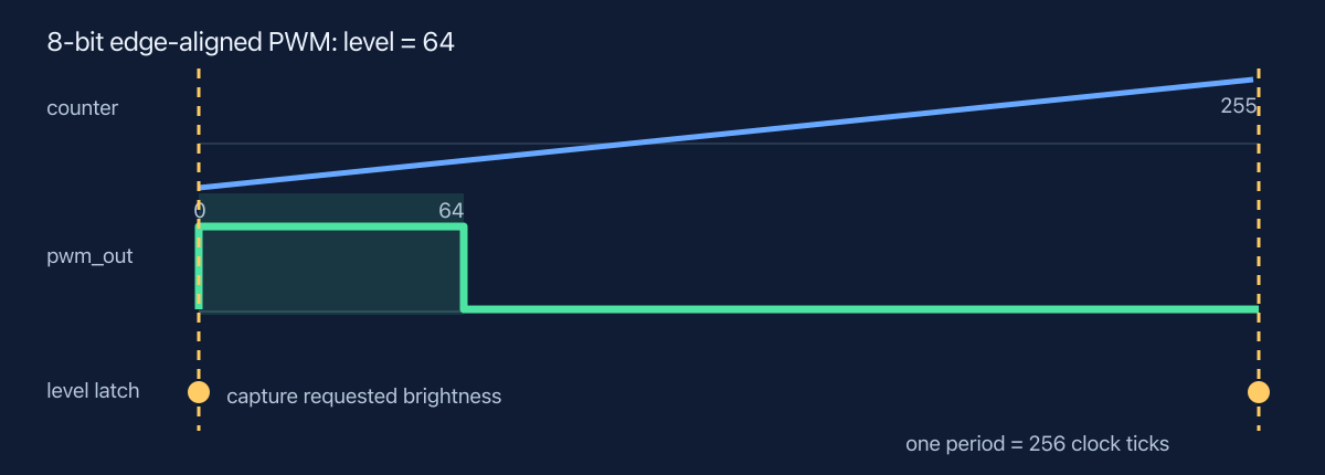
The testbench checks codes 1, 64, 128, 254, and 255. The first four produce the same number of high clocks as the code. The explicit full-scale saturation rule maps 255 to all 256 clocks. Keeping that convention in the assertion prevents a future cleanup from silently changing what “fully on” means.
Download the complete module and testbench
The reference project includes synthesizable RTL, a self-checking VHDL-2008 testbench, the BCM and HUB75 companion designs, and a Makefile tested with Icarus VHDL.
Synthesis and timing checklist
- Constrain the real input clock; do not rely on a simulation period alone.
- Use a clock enable when slowing the counter rather than routing a fabric-generated clock.
- Register the output when it must meet a strict external setup or hold relationship.
- Confirm the LED polarity in the board schematic and constraints.
- Measure the physical output with a scope at minimum, midpoint, and maximum codes.
FPGA LED controller tutorial series
This article is part of the FPGA LED Controller Tutorials learning path. Continue with PWM vs. BCM, the HUB75 timing calculator, or VHDL-2008 verification.
Leave a Reply