Binary-coded modulation (BCM) produces LED brightness with weighted bitplanes instead of one comparator per channel. It is a natural fit for FPGAs driving many LEDs because the same scheduler can service an entire row, bank, or panel. This tutorial derives the timing, implements an 8-bit engine in VHDL-2008, and proves its most important property: an input value of N produces exactly N illuminated base-time slots per cycle.
BCM in one equation
VHDL-2008 reference implementation
This article uses synthesizable VHDL-2008. The complete tested VHDL bundle is linked below; adapt clock constraints, I/O standards, and timing parameters to the target board and panel.
library ieee;
use ieee.std_logic_1164.all;
use ieee.numeric_std.all;

entity bcm_led is
  generic (BITS : positive := 8);
  port (
    clk         : in  std_logic;
    rst         : in  std_logic;
    level       : in  unsigned(BITS - 1 downto 0);
    led_out     : out std_logic;
    cycle_start : out std_logic
  );
end entity;

architecture rtl of bcm_led is
  signal plane        : natural range 0 to BITS - 1 := 0;
  signal dwell        : natural range 0 to 2 ** BITS - 1 := 0;
  signal active_level : unsigned(BITS - 1 downto 0) := (others => '0');
begin
  process (clk)
    variable plane_ticks : natural;
  begin
    if rising_edge(clk) then
      if rst = '1' then
        plane        <= 0;
        dwell        <= 0;
        active_level <= (others => '0');
      else
        plane_ticks := 2 ** plane;
        if dwell = plane_ticks - 1 then
          dwell <= 0;
          if plane = BITS - 1 then
            plane        <= 0;
            active_level <= level;
          else
            plane <= plane + 1;
          end if;
        else
          dwell <= dwell + 1;
        end if;
      end if;
    end if;
  end process;

  led_out     <= active_level(plane);
  cycle_start <= '1' when plane = 0 and dwell = 0 else '0';
end architecture;
Download the VHDL-2008 FPGA LED controller examples
An unsigned B-bit value is the sum of its set bits. Bit 0 is worth 1, bit 1 is worth 2, bit 2 is worth 4, and so on. BCM displays each bitplane for that same weight. The total cycle contains:
1 + 2 + 4 + … + 2B-1 = 2B − 1 base slots
For 8-bit BCM, the complete cycle is 255 base slots. A pixel value of 173 is binary 10101101, so it is on during planes worth 128, 32, 8, 4, and 1 slots. Those weights add back to 173.
The scheduler
The controller needs a plane index and a dwell counter. Plane 0 lasts one tick, plane 1 lasts two, and plane 7 lasts 128. When the dwell counter reaches the weight of the current plane, advance to the next plane.
The requested level is copied only at the end of a complete cycle. That prevents one cycle from containing lower planes from an old value and upper planes from a new one.
Choose the base tick
If the base-tick frequency is Fbase, the BCM cycle rate is Fbase divided by 255 for 8 bits. A 1 MHz base tick produces about 3.92 kHz. In a multiplexed display, divide again by the number of row groups and include shifting, latching, and blanking overhead.
Do not assume the FPGA clock itself can be the base tick. A 10 ns least-significant plane may be shorter than the external driver, level shifter, wiring, or LED output can settle. Generate a clock-enable pulse that establishes a practical minimum slot.
A self-checking BCM test
Run the task for boundary values 0, 1, 127, 128, 254, and 255, plus randomized values. The equality between the code and total illuminated slots is a compact specification of correct BCM behavior.
Plane order is a design choice
Least-significant-bit first is easy to understand, but it places the longest dark or light interval at the end. You can reorder planes, split the most-significant plane into several smaller visits, or interleave rows to distribute energy more evenly. The sum of dwell times must remain unchanged. Reordering helps camera behavior and peak-current distribution, but it cannot rescue a refresh budget that is fundamentally too small.
Scaling from one LED to a matrix
- Store one brightness word per color channel in a framebuffer.
- For the active plane, transmit the corresponding bit from every pixel in the row.
- Blank outputs, latch the shifted bits, select the row, and enable the plane for its weighted dwell.
- Swap framebuffers only when the full frame completes.
- Verify the refresh budget before increasing color depth.
BCM and conventional PWM deliver the same average duty cycle; they organize time differently. For the architectural tradeoff between external bitplanes and drivers that generate grayscale internally, read External PWM Bitframes vs. 16-Bit Grayscale.
Official references
- AMD Vivado Design Suite User Guide: Synthesis (UG901)
- Intel Quartus Prime Pro Edition User Guide: Design Recommendations
The complete 8-bit timeline
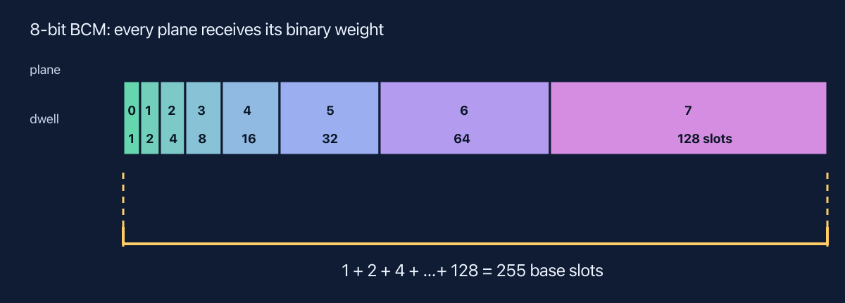
The diagram makes the main engineering constraint visible: the most-significant plane occupies roughly half of the cycle while the least-significant plane gets one base slot. The minimum usable slot therefore limits effective depth. If shifting, blanking, or output settling cannot fit around that slot, the framebuffer may say eight bits while the optics deliver fewer.
Download and prove the scheduler
The downloadable test drives 1, 64, 127, 128, 254, and 255. It counts exactly 255 samples for each active value and fails unless illuminated slots equal the requested unsigned code.
Implementation checklist
- Define whether a base slot includes or excludes blanking and latch overhead.
- Capture a new level only at a full BCM-cycle boundary.
- Verify every plane duration independently as well as the total on-slot sum.
- Calculate refresh after multiplying by the row-group count.
- Measure the optical waveform when plane order matters to cameras.
FPGA LED controller tutorial series
This article is part of the FPGA LED Controller Tutorials learning path. Continue with PWM vs. BCM, the HUB75 timing calculator, or VHDL-2008 verification.
Leave a Reply