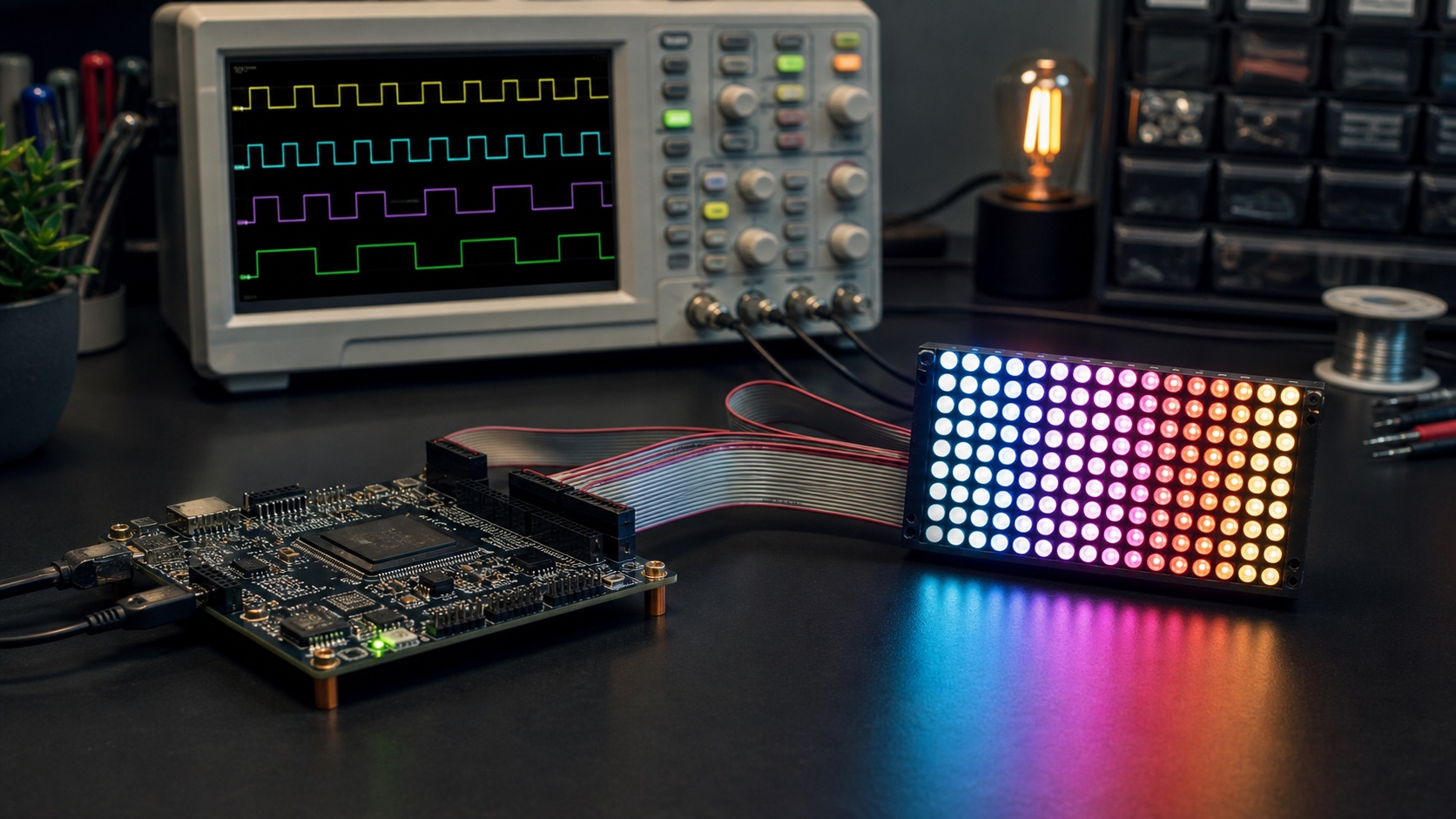
An FPGA can drive an LED display in two very different ways: send every PWM bitplane on a strict schedule, or send complete intensity values to a driver that generates PWM internally. The pixels may look identical, but the timing, bandwidth, and failure modes are not.
The difference in one sentence
VHDL-2008 reference implementation
This article uses synthesizable VHDL-2008. The complete tested VHDL bundle is linked below; adapt clock constraints, I/O standards, and timing parameters to the target board and panel.
library ieee;
use ieee.std_logic_1164.all;
use ieee.numeric_std.all;

entity bcm_led is
  generic (BITS : positive := 8);
  port (
    clk         : in  std_logic;
    rst         : in  std_logic;
    level       : in  unsigned(BITS - 1 downto 0);
    led_out     : out std_logic;
    cycle_start : out std_logic
  );
end entity;

architecture rtl of bcm_led is
  signal plane        : natural range 0 to BITS - 1 := 0;
  signal dwell        : natural range 0 to 2 ** BITS - 1 := 0;
  signal active_level : unsigned(BITS - 1 downto 0) := (others => '0');
begin
  process (clk)
    variable plane_ticks : natural;
  begin
    if rising_edge(clk) then
      if rst = '1' then
        plane        <= 0;
        dwell        <= 0;
        active_level <= (others => '0');
      else
        plane_ticks := 2 ** plane;
        if dwell = plane_ticks - 1 then
          dwell <= 0;
          if plane = BITS - 1 then
            plane        <= 0;
            active_level <= level;
          else
            plane <= plane + 1;
          end if;
        else
          dwell <= dwell + 1;
        end if;
      end if;
    end if;
  end process;

  led_out     <= active_level(plane);
  cycle_start <= '1' when plane = 0 and dwell = 0 else '0';
end architecture;
Download the VHDL-2008 FPGA LED controller examples
External PWM sends a timeline; internal grayscale sends a value. In the first architecture, the controller decides exactly when each bitplane is visible. In the second, the controller writes an intensity word and the driver turns that value into pulses.
| Question | External PWM bitframes | 16-bit grayscale driver |
|---|---|---|
| What crosses the interface? | One bit per channel, once per bitplane | One complete intensity word per channel |
| Who schedules PWM? | FPGA or microcontroller | LED driver |
| Traffic for a static image | Continuous | Usually only the initial load |
| Timing freedom | High | Defined by the driver |
| Main design risk | Missed real-time deadlines | Update and latch behavior |
External PWM bitframes
With external PWM, the FPGA or microcontroller decomposes every channel value into bitplanes. For an N-bit value, plane 0 contains every channel’s least-significant bit, plane 1 contains the next bit, and so on. Each plane is displayed for a time proportional to its binary weight: 1, 2, 4, 8 … up to 2N-1.
This technique is also called binary coded modulation, bit-angle modulation, or bitplane PWM. The display driver can be simple—it shifts, latches, and enables outputs—but the controller must continuously meet the shift-clock, latch, row-select, blanking, and output-enable deadlines.
Small VHDL example: select one bitplane
The extraction is easy. The harder logic is the scheduler around it: load a plane, blank the outputs, latch it, select the row, enable it for the weighted interval, and repeat without jitter.
Driver-managed 16-bit grayscale
A grayscale-capable driver accepts a complete intensity word for each channel and stores it internally. A local timing engine compares those stored values against a grayscale counter and produces the output pulses. The controller updates the image; the driver keeps refreshing it.
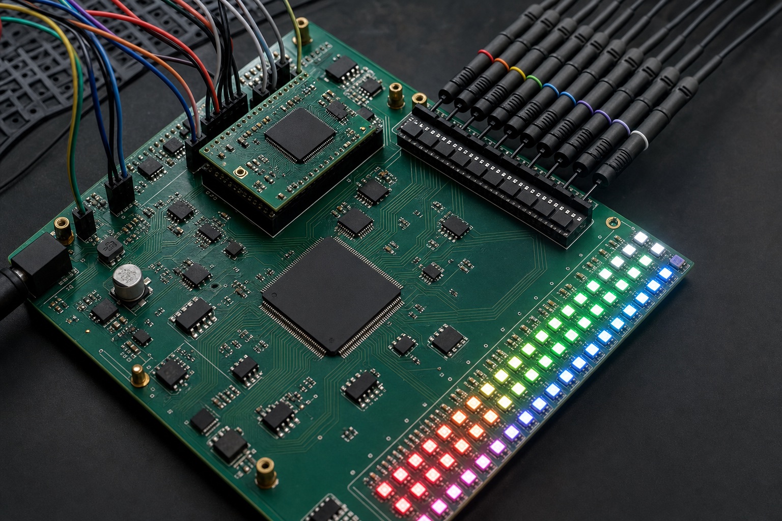
This turns a continuous waveform-generation job into a frame-update job. Once a frame is loaded, the driver can display it while the FPGA calculates the next image, services another interface, or simply waits.
Small C example: write one 16-bit channel
A real driver may pack channels differently and may require a latch or frame-boundary signal, so its datasheet still controls the exact transaction.
Bandwidth: count payload bits first
For C color channels, B bitplanes, and a PWM refresh rate of F, the minimum external-bitplane payload is:
external payload = C × B × F bits/s
A 64 × 32 RGB panel has 6,144 channels. At 12-bit color and 200 complete PWM cycles per second, the raw payload is about 14.7 Mbit/s before latch, blanking, addressing, or protocol overhead. That traffic continues even when the picture is static.
For a 16-bit grayscale driver updated at U frames per second:
grayscale update payload = C × 16 × U bits/s
The same panel updated at 60 frames per second needs about 5.9 Mbit/s of raw intensity data. Hold the image still and the update traffic can fall to zero while the driver continues its PWM. Update all 16 bits at 200 frames per second, however, and the raw payload rises to about 19.7 Mbit/s. Internal PWM is not automatically lower bandwidth; its advantage is that display refresh is decoupled from image updates.
Timing pressure grows faster than bit depth
The bitplane count grows linearly with resolution, but the weighted time range grows exponentially. A 12-bit PWM cycle contains 4,095 least-significant-bit time units; a 16-bit cycle contains 65,535. Ignoring scan multiplexing and overhead, the shortest slot is:
TLSB = 1 ÷ [F × (2B − 1)]
At 200 Hz and 12 bits, that is about 1.22 µs before row scanning, blanking, latching, and settling time take their share. This is why the least-significant planes are often where a design first shows brightness errors, flicker, or lost effective bits.
What each architecture buys you
External PWM
- Full timing control: choose plane order, blanking, refresh strategy, and effective depth.
- Room to experiment: temporal dithering, camera synchronization, and custom compensation live in FPGA logic.
- Simple output devices: shift-register-style drivers can be inexpensive and transparent.
- The cost: continuous traffic, more memory and scheduling logic, and hard real-time deadlines.
Internal grayscale PWM
- Lower controller workload: send intensity data and let dedicated hardware perform modulation.
- Stable local timing: PWM is isolated from unrelated controller stalls and arbitration.
- Efficient static display: stored values can be reused indefinitely.
- The cost: less control, a more capable driver, and device-specific latch and buffering rules.
Which should you choose?
Choose external PWM when modulation itself is part of the design: you need deterministic custom timing, unusual plane ordering, camera-aware refresh, or the freedom to trade color depth against refresh dynamically. It is a natural fit when the FPGA already has enough I/O bandwidth, RAM, and timing margin.
Choose a grayscale driver when you want a clean frame-oriented boundary, stable high-resolution brightness, and less continuous work in the controller. Verify whether the device double-buffers its grayscale memory, when new data takes effect, whether outputs must be blanked during latching, and how its PWM clock relates to your required refresh rate.
The deciding question is not simply “How many bits?” It is where should the timing contract live? External bitframes keep it in programmable logic. A grayscale driver moves it next to the LEDs.
FPGA LED controller tutorial series
This article is part of the FPGA LED Controller Tutorials learning path. Continue with PWM vs. BCM, the HUB75 timing calculator, or VHDL-2008 verification.
Leave a Reply